 Using BeagleboneBlack with Maxim 1-Wire devices
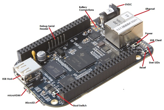
This page is about using 1-wire devices and the beaglebone black (BB) mini pc.
A rocket solid system, for me an uptime of 2 years is not a problem (UPS)
Software
Install Debian os on the BB: https://beagleboard.org/latest-images
OWFS software: apt-get install ow-shell owfs-common owserver
I2C to 1wire interface with the DS2482-100 or DS2482-800
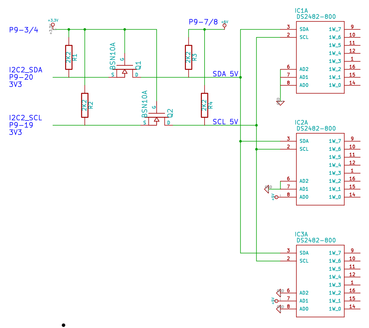 All GPIO's of the BB have a logic level of 3.3V. To use the 1wire device at 5V a logic bidirectional level shift is necessary, this can be done with the use of a nmos FET, see the Philips application note an97055
In this schematic there are 3 DS2482-800 devices on a I2C bus, all with there own address at pins 6,7,8.
To probe the I2C bus:
/usr/sbin/i2cdetect -r 1
WARNING! This program can confuse your I2C bus, cause data loss and worse!
I will probe file /dev/i2c-1 using read byte commands.
I will probe address range 0x03-0x77.
Continue? [Y/n] y
     0  1  2  3  4  5  6  7  8  9  a  b  c  d  e  f
00:          -- -- -- -- -- -- -- -- -- -- -- -- --
10: -- -- -- -- -- -- -- -- 18 19 1a -- -- -- -- --
20: -- -- -- -- -- -- -- -- -- -- -- -- -- -- -- --
30: -- -- -- -- -- -- -- -- -- -- -- -- -- -- -- --
40: -- -- -- -- -- -- -- -- -- -- -- -- -- -- -- --
50: -- -- -- -- UU UU UU UU -- -- -- -- -- -- -- --
60: -- -- -- -- -- -- -- -- -- -- -- -- -- -- -- --
Address 000 at IC1 will be 18.
OWFS
| Start owserver: /usr/bin/owserver --i2c=/dev/i2c-1:ALL
owdir example, it will show 24 busses and 3 ds1820: |
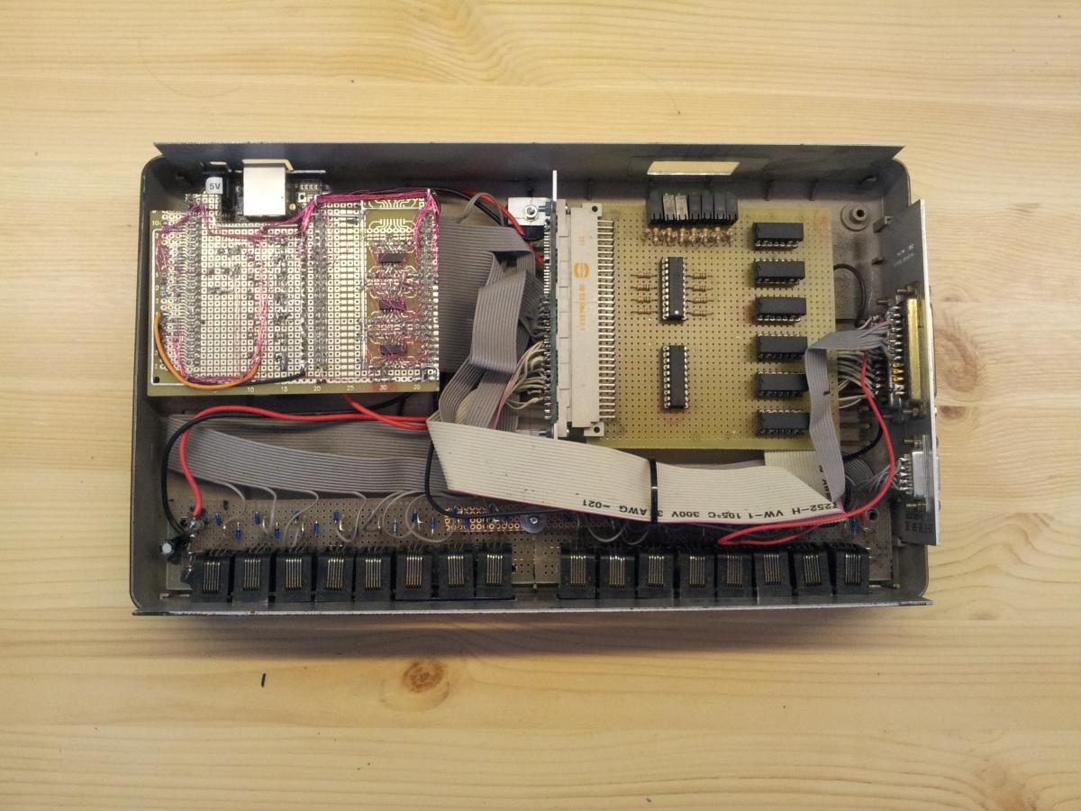
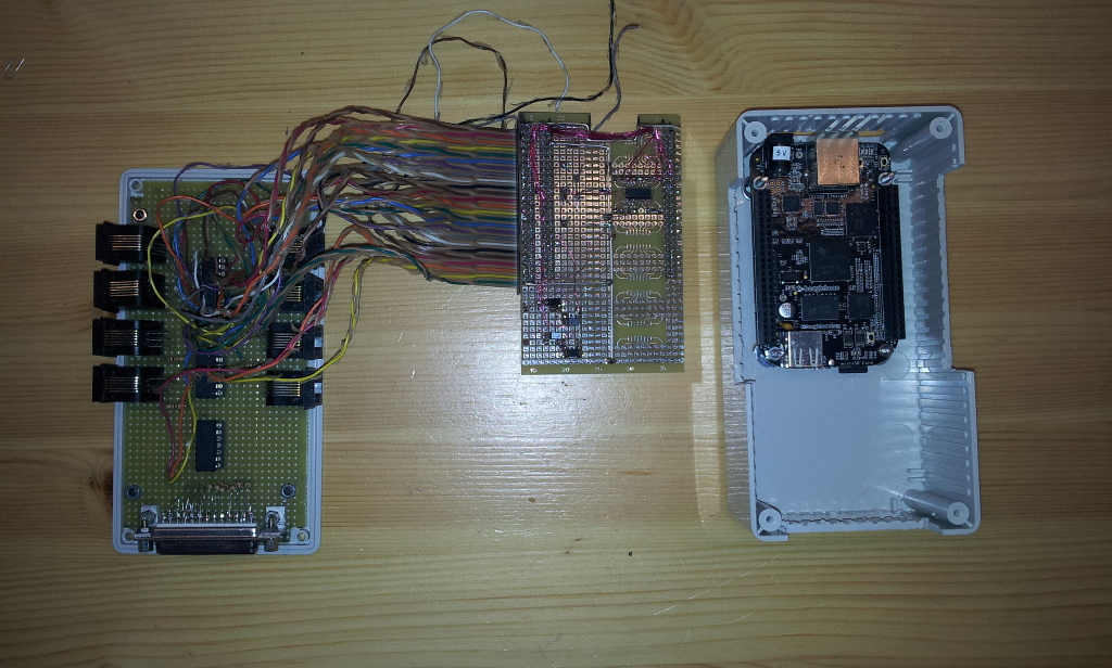
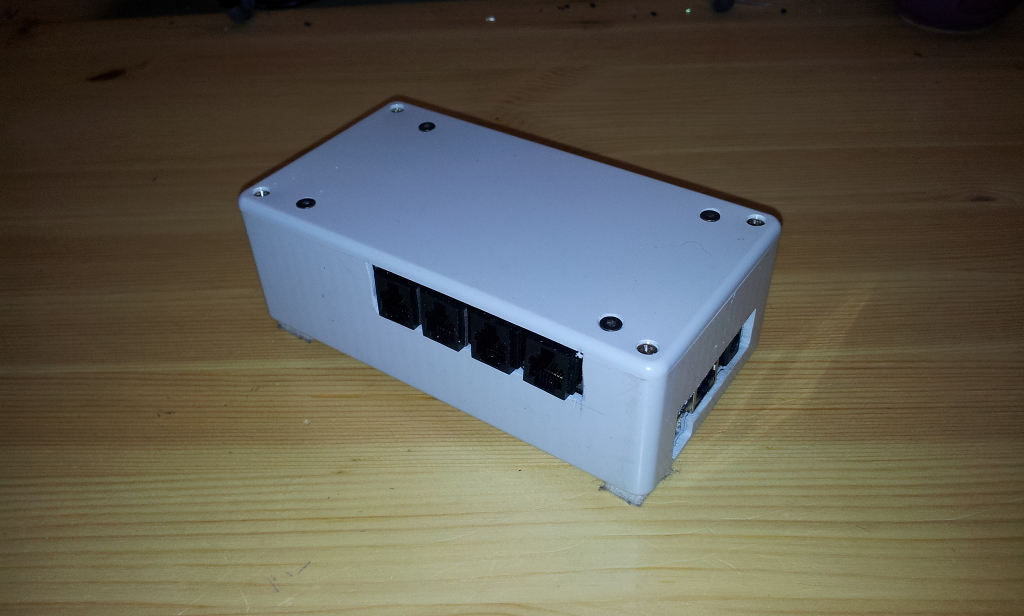
My project, it has 16/24 1-wire buses, 8 IO outputs for solidstate ralays, 6 reedrelays and 4 ADC inputs.
Mini version, 8 1wire buses (ds2482-800), 8 IO outputs (2 relais) and 2 ADC inputs
|
GPIO ports
Free available GPIO ports of the BB which i am using to drive solidstate and reed relays:
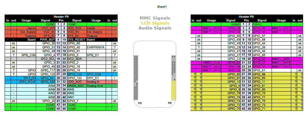
| Address | BB connector |
|---|---|
| 45 | P8_11 |
| 44 | P8_12 |
| 23 | P8_13 |
| 26 | P8_14 |
| 47 | P8_15 |
| 46 | P8_16 |
| 27 | P8_17 |
| 65 | P8_18 |
| 60 | P9_12 |
| 50 | P9_14 |
| 48 | P9_15 |
| 51 | P9_16 |
| 49 | P9_23 |
| 115 | P9_27 |
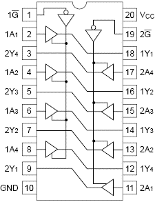 I've added a buffer 74hct244 on these GPIO outputs, to drive solidstate and reedrelays directly. 74hct is ttl level (2V).
Don't use this for inputs, max input voltage is 3.3V!
To alter state to high of port 45 at pin P8 11:
echo 45 > /sys/class/gpio/export
echo high > /sys/class/gpio/gpio45/direction
ADC ports
 MAX input voltage of the ADC ports AIN0-6 is 1.8V.
To enable analog AIN ports:
echo cape-bone-iio > /sys/devices/bone_capemgr.9/slots.
Only ports AIN 1 4 5 6 are free available, the rest is being used for a LCD touchscreen cape.
To read the voltageat AIN1:
cat /sys/devices/ocp.2/helper.14/AIN1
There is also a raw counter:
cat /sys/bus/iio/devices/iio\:device0/in_voltage1_raw. For me the correction factor with the use of the voltage divider was about 0.00135.
Hardware:
Conrad:
- 532665 PB Fastener Wire spool set Wire spool set
- 531397 SMD EURO-PCB 160 X 100 X 1.6MM